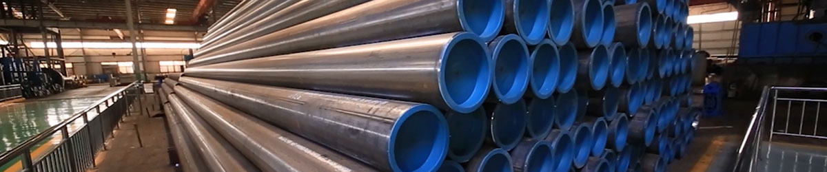
1. Bend tubing:
Tube bending is the umbrella term for metal forming processes used to permanently form pipes or tubing. One must differentiate between form-bound and free form-bending procedures, as well as between heat supported and cold forming procedures.
2. Processes:
Tube bending as a process starts with loading a tube into a tube or pipe bender and clamping it into place between two dies, the clamping block and the forming die. The tube is also loosely held by two other dies, the wiper die and the pressure die.
The process of tube bending involves using mechanical force to push stock material pipe or tubing against a die, forcing the pipe or tube to conform to the shape of the die. Often, stock tubing is held firmly in place while the end is rotated and rolled around the die. Other forms of processing including pushing stock through rollers that bend it into a simple curve.[2] For some tube bending processing, a mandrel is placed inside the tube to prevent collapsing. The tube is held in tension by a wiper die to prevent any creasing during stress. A wiper die is usually made of a softer alloy such as aluminum or brass to avoid scratching or damaging the material being bent.
Press bending:
Press bending is probably the first bending process used on cold pipes and tubing. In this process a die in the shape of the bend is pressed against the pipe forcing the pipe to fit the shape of the bend. Because the pipe is not supported internally there is some deformation of the shape of the pipe, resulting in an oval cross section. This process is used where a consistent cross section of the pipe is not required. Although a single die can produce various shapes, it only works for one size tube and radius.
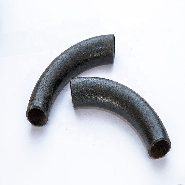
Rotary draw bending:
Full tooling for rotary draw bending
Rotary draw bending (RDB) is a precise technology, since it bends using tooling or "die sets" which have a constant center line radius (CLR), alternatively indicated as mean bending radius (Rm).
Roll bending:
During the roll bending process the pipe, extrusion, or solid is passed through a series of rollers (typically three) that apply pressure to the pipe gradually changing the bend radius in the pipe. The pyramid style roll benders have one moving roll, usually the top roll. Double pinch type roll benders have two adjustable rolls, usually the bottom rolls, and a fixed top roll. This method of bending causes very little deformation in the cross section of the pipe. This process is suited to producing coils of pipe as well as long gentle bends like those used in truss systems.
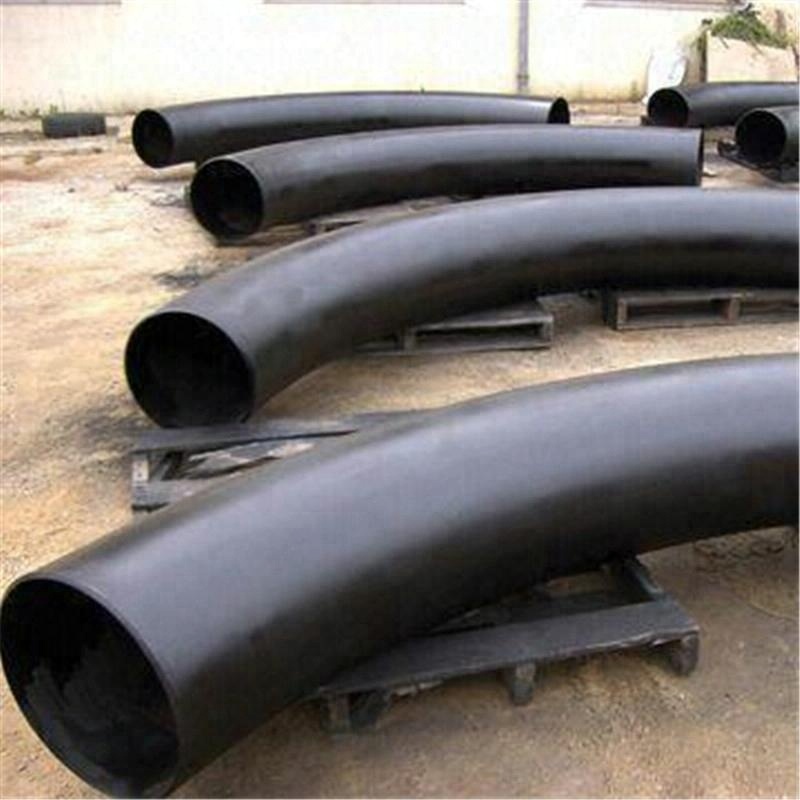
Induction bending:
An induction coil is placed around a small section of the pipe at the bend point. It is then induction heated to between 800 and 2,200 degrees Fahrenheit (430 and 1,200 C). While the pipe is hot, pressure is placed on the pipe to bend it. The pipe can then be quenched with either air or water spray or be cooled against ambient air.
Induction bending is used to produce bends for a wide range of applications, such as (thin walled) pipe lines for both the upstream and down stream and on- and off shore segments of the petrochemical industry, large radius structural parts for the construction industry, thick walled, short radius bends for the power generating industry and city heating systems.
Big advantages of induction bending are:
no need for mandrels
bend radii and angles (1°-180°) can be freely selected
highly accurate bend radii and angles
accurate pipe spools can easily be produced
significant savings can be obtained on field welds
wide range of pipe sizes can be accommodated in one machine (1” OD thru 80”OD)
excellent wall thinning and ovality values
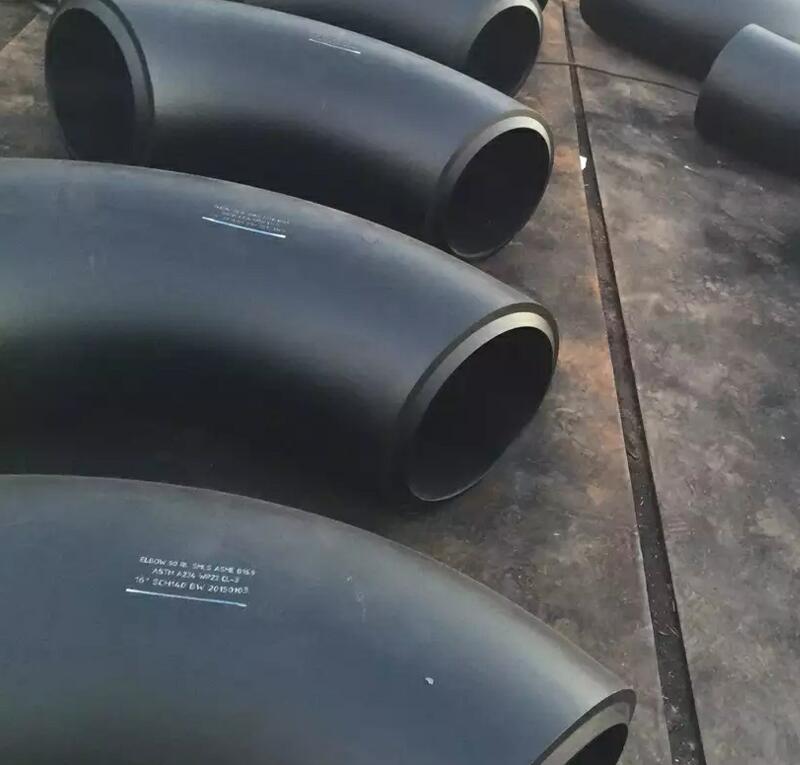
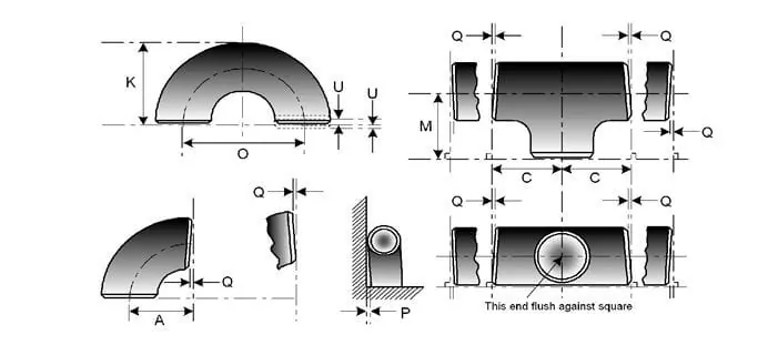
For Wrought Product (WP) Dimension is covered in
ASME B16.9- which is standard for Factory-made Wrought Butt-welding Fittings for size NPS 1⁄₂ to NPS 48” and
And B16.28- which is standard for Wrought Steel Butt-Welding Short Radius Elbows and Returns for size NPS 1⁄₂ to NPS 24”
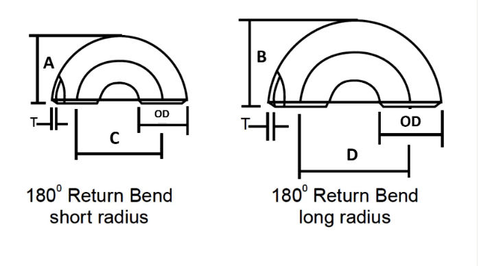
| NOMINAL PIPE SIZE | OUTSIDE DIAMETER | BACK TO FACE | CENTER TO CENTER | ||
| Inch. | OD | A | B | C | D |
| 1/2 | 21.3 | 48 | – | 76 | – |
| 3/4 | 26.7 | 43 | – | 57 | – |
| 1 | 33.4 | 56 | 41 | 76 | 51 |
| 1 1/4 | 42.2 | 70 | 52 | 95 | 64 |
| 1 1/2 | 48.3 | 83 | 62 | 114 | 76 |
| 2 | 60.3 | 106 | 81 | 152 | 102 |
| 2 1/2 | 73 | 132 | 100 | 191 | 127 |
| 3 | 88.9 | 159 | 121 | 229 | 152 |
| 3 1/2 | 101.6 | 184 | 140 | 267 | 178 |
| 4 | 114.3 | 210 | 159 | 305 | 203 |
| 5 | 141.3 | 262 | 197 | 381 | 254 |
| 6 | 168.3 | 313 | 237 | 457 | 305 |
| 8 | 219.1 | 414 | 313 | 610 | 406 |
| 10 | 273.1 | 518 | 391 | 762 | 508 |
| 12 | 323.9 | 619 | 467 | 914 | 610 |
| 14 | 355.6 | 711 | 533 | 1067 | 711 |
| 16 | 406.4 | 813 | 610 | 1219 | 813 |
| 18 | 457.2 | 914 | 686 | 1372 | 914 |
| 20 | 508 | 1016 | 762 | 1524 | 1016 |
| 22 | 559 | 1118 | 838 | 1676 | 1118 |
| 24 | 610 | 1219 | 914 | 1829 | 1219 |
Pipe Fittings Dimensions Tolerance as per ASME B16.9
| NOMINAL PIPE SIZE | ALL FITTINGS | ALL FITTINGS | ALL FITTINGS | ELBOWS AND TEES | 180 DEG RETURN BENDS | 180 DEG RETURN BENDS | 180 DEG RETURN BENDS | REDUCERS | CAPS |
| NPS | O.D. at Bevel (1), (2) | I.D. at End (1), (3), (4) |
Wall Thickness (3) | Centre-to-End Dimension A,B,C,M | Centre-to-Centre O | Back-to-Face K | Alignment of Ends U | Overall Length H | Overall Length E |
| ½ to 2½ | 0.06 -0.03 |
0.03 | Not less than 87.5% of nominal thickness | 0.06 | 0.25 | 0.25 | 0.03 | 0.06 | 0.12 |
| 3 to 3 ½ | 0.06 | 0.06 | Not less than 87.5% of nominal thickness | 0.06 | 0.25 | 0.25 | 0.03 | 0.06 | 0.12 |
| 4 | 0.06 | 0.06 | Not less than 87.5% of nominal thickness | 0.06 | 0.25 | 0.25 | 0.03 | 0.06 | 0.12 |
| 5 to 8 | 0.09 -0.06 |
0.06 | Not less than 87.5% of nominal thickness | 0.06 | 0.25 | 0.25 | 0.03 | 0.06 | 0.25 |
| 10 to 18 | 0.16 -0.12 |
0.12 | Not less than 87.5% of nominal thickness | 0.09 | 0.38 | 0.25 | 0.06 | 0.09 | 0.25 |
| 20 to 24 | 0.25 -0.19 |
0.19 | Not less than 87.5% of nominal thickness | 0.09 | 0.38 | 0.25 | 0.06 | 0.09 | 0.25 |
| 26 to 30 | 0.25 -0.19 |
0.19 | Not less than 87.5% of nominal thickness | 0.12 | … | … | … | 0.19 | 0.38 |
| 32 to 48 | 0.25 -0.19 |
0.19 | Not less than 87.5% of nominal thickness | 0.19 | … | … | … | 0.19 | 0.38 |
Nickel Alloy
ASTM / ASME SB 336 UNS 2200 ( NICKEL 200 ), UNS 2201 (NICKEL 201 ), UNS 4400 (MONEL 400 ), UNS 8020 ( ALLOY 20 / 20 CB 3, UNS 8825 INCONEL (825), UNS 6600 (INCONEL 600 ), UNS 6601 ( INCONEL 601 ), UNS 6625 (INCONEL 625), UNS 10276 ( HASTELLOY C 276 )
Stainless Steel
ASTM / ASME SA 403 GR WP “S” / “W” / ” WX” 304 , 304L, 304H, 304N, 304LN, 309, 310H, 316, 316H, 317, 317L, 321, 321H, 347, 347 H.
Duplex Steel
ASTM / ASME SA 815 UNS NO.S 31803, S 32205, S 32550, S 32750, S 32760.
Carbon Steel
ASTM / ASME A 234 WPB, WPC ASTM / ASME A 860 WPHY 42, WPHY 46, WPHY 52, WPH 60, WPHY 65 & WPHY 70.
Alloy Steel
ASTM / ASME A 234 WP 1, WP 5, WP 9, WP 11, WP 12, WP 22, WP 23, WP 91.
| Chemical Composition Content | Mechanical Properties | ||||||||||
| Material NO | C | Mn | Si | S | P | Cr | Mo | Ni | Tensile strength | Yield strength | Elongation |
| A234 WPB | ≤0.3 | 0.29-1.06 | ≥0.1 | ≤0.058 | ≤0.05 | / | / | / | 415-585 | ≥240 | ≥30 |
| A234 WP5 | ≤0.15 | ≤0.6 | ≤0.5 | ≤0.04 | ≤0.03 | 4-6 | 0.44-0.65 | / | 415-585 | ≥205 | ≥20 |
| A403 WP304 | ≤0.08 | ≤2 | ≤1 | ≤0.040 | ≤0.030 | 18-20 | / | 8-11 | ≥515 | ≥205 | ≥30 |
| A403 WP316L | ≤0.03 | ≤2 | ≤1 | ≤0.045 | ≤0.03 | 16-18 | 2-3 | 10-15 | ≥485 | ≥170 | ≥30 |
| WPHY60 | ≤0.20 | 1-1.45 | 0.15-0.4 | ≤0.015 | ≤0.030 | / | / | / | ≥515 | ≥415 | / |
Light Oiling, Black Painting, PE /3PE Anti-corrosion Coating
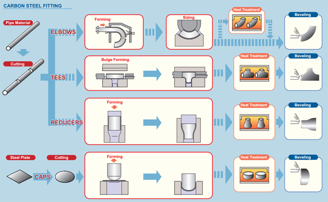
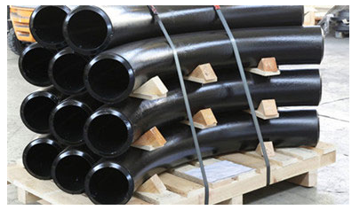
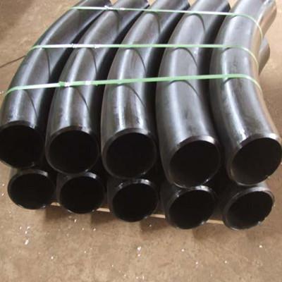
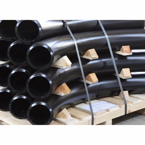
Hot induction bend planking requirements
We focus on every procedure to assure quality ,the package we usually take is plank the steel pipe elbows with environmental poly bags,and then in free fumigation wooden cases or wooden plate.we also accept customized package such as OEM by negotiation.
- Material shall be packed ready for export in a manner which allows easy handling and prevents damage,vendor shall submit their standard packing procedure to purchaser for approval.
- Open ends of fitting and flanges shall be supplied with heavy duty plastic protective plugs or caps.For beveled ends ,the caps shall protect the full area of the bevel.
- Water proof barrier material shall be used for stainless steel material to protect against chlorine attack by exposure to salt water atmosphere.
- Carbon steel and stainless steel items are not allowed to be stored together and shall be packed separately.